
Page 61 - 건축구조 Vol. 29 / No. 04
P. 61
The Londoner hotel Project focus Project focus The Londoner hotel
Digging deep: design and construction of The Londoner hotel
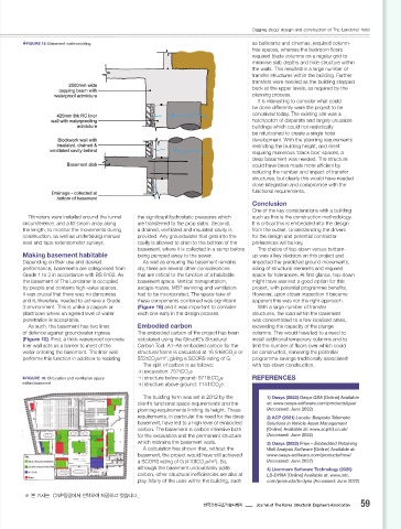
to address these concerns, balancing preheat, FIGURE 13: Predicted ground movements Monitoring FIGURE 15: Basement waterproo ng as ballrooms and cinemas, required column-
heat input and interpass temperatures to A monitoring regime was implemented free spaces, whereas the bedroom oors
achieve reduced hardness levels while throughout the build to record actual required blade columns on a regular grid to
maintaining toughness of the welded material. ground movements. Baseline monitoring minimise slab depths and hide structure within
Heat input was restricted during fabrication was carried out before the demolition of the the walls. This resulted in a large number of
and this was closely monitored throughout the existing buildings on the site. The predicted transfer structures within the building. Further
welding process. A high preheat of 125°C was movements from the analysis were then used transfers were needed as the building stepped
used with a maximum interpass temperature of as the basis to set trigger levels for ongoing back at the upper levels, as required by the
228°C; this meant that, on occasions, welding monitoring, with readings taken twice weekly. planning process.
had to be stopped to prevent excessive heat To monitor movements, ground-level It is interesting to consider what could
build-up. settlement targets, targets for 3D building be done diff erently were the project to be
Before forming the trusses, a full-scale test movements and inclinometers were installed conceived today. The existing site was a
weld was undertaken to demonstrate that the on the pile wall. All the data was available via hotchpotch of disparate and largely unusable
welds would comply. Samples were taken a web portal (Figure 14) and compared with buildings which could not realistically
before and after the test weld, with Charpy the trigger values, with the construction and be refurbished to create a single hotel
impact tests carried out to ensure that the Arup engineering teams noti ed of any issues. development. With the planning requirements
toughness of the parent material had not Overall, the observed ground movements restricting the building height, and client
dropped off signi cantly during the procedure. were generally consistent with the predictions, requiring numerous ‘black box’ spaces, a
The largest FPBWs required up to 300 with 25–30mm of settlement observed close deep basement was needed. The structure
passes to complete. Analysis to the excavation, reducing with increased could have been made more effi cient by
To ensure that all welds met the design Ground movement impact assessments were distance. reducing the number and impact of transfer
speci cation, a strict non-destructive testing needed to gain approval from various parties. structures, but clearly this would have needed
(NDT) procedure was implemented as follows: These assessments were undertaken in a UKPN high-voltage power cable close integration and compromise with the
1) A visual inspection of every weld pass was staged approach as follows: Many of the utilities surrounding the basement functional requirements.
undertaken by the welder, checking for 1) A simple 2D retaining wall analysis was were diverted before construction. However,
cracks, pits, and various other aspects of the performed in Frew . This was used to quickly there was one particular utility within the site Conclusion
3
weld. consider the eff ect of diff erent construction boundary that could not be diverted: a UKPN One of the key considerations with a building
2) A hold time, de ned as the time after sequences and design options. tunnel, located 14m below the ground and Tiltmeters were installed around the tunnel the signi cant hydrostatic pressures which such as this is the construction methodology.
weld completion before NDT testing may 2) A 2D FE analysis was carried out on a ‘slice’ containing a number of high-voltage cables circumference, and a tilt-beam array along are transferred to the prop slabs. Second, It is critical this is embedded into the design
commence, of either 24 or 48 hours had through the basement using LS Dyna . This serving the substation within Leicester Square the length, to monitor the movements during a drained, ventilated and insulated cavity is from the outset. Understanding the drivers
4
to be observed depending on the carbon was more detailed than Stage 1, accounting and subsequently supplying the West End construction, as well as undertaking manual provided. Any groundwater that gets into the for the design and potential contractor
equivalence of the steel to allow any delayed for sway (due to ground-level variation across of London, which cut across the northwest level and tape extensometer surveys. cavity is allowed to drain to the bottom of the preferences will be key.
cracking to occur. the site) and heave eff ects, but extrapolation corner of the site. basement, where it is collected in a sump before The choice of top-down versus bottom-
3) Magnetic particle inspection was used to was required for corner eff ects. The tunnel impacted the position of the Making basement habitable being pumped away to the sewer. up was a key decision on this project and
detect surface and shallow subsurface 3) Once a preferred design and construction basement piles, which were located as close Depending on their use and desired As well as ensuring the basement remains impacted the predicted ground movements,
discontinuities. Undertaken on 100% of all sequence had been determined, a full 3D as possible to the tunnel. This meant there performance, basements are categorised from dry, there are several other considerations sizing of structural elements and required
large butt welds, this involves applying a FE model of the basement construction was was a risk of: Grade 1 to 3 in accordance with BS 8102. As that are critical to the function of a habitable space for tolerances. At rst glance, top-down
magnetic eld to the weld. A wet suspension analysed using LS Dyna. With all stages of | striking the tunnel during the pile the basement of The Londoner is occupied basement space. Vertical transportation, might have seemed a good option for this
of iron lings is applied to the weld and, if a the construction sequence modelled, the installation by people and contains high-value spaces, escape routes, MEP servicing and ventilation project, with potential programme bene ts.
discontinuity is present, magnetic ux leakage model took approx. one week to run (plus | excavation-induced movements damaging it was crucial that there was no dampness had to be incorporated. The space take of However, upon closer inspection it became
attracts the iron lings. time to review and process the results), so it the tunnel structure. and it, therefore, needed to achieve a Grade these components combined was signi cant apparent this was not the right approach.
4) Ultrasonic testing was undertaken on 100% was important to minimise the changes to the 3 environment. This is unlike a carpark or (Figure 16) and it was important to consider With a large number of transfer
of all large butt welds. This involves projecting basement design where possible. One of the most complex assessments plantroom where an agreed level of water each one early in the design process. structures, the load within the basement
an ultrasonic sound wave through the weld undertaken was the impact of piling and penetration is acceptable. was concentrated to a few localised areas,
at varying angles (0°, 45° and 60° normal to Ground movements adjacent to the excavating adjacent to this asset. Usually, As such, the basement has two lines Embodied carbon exceeding the capacity of the plunge
the steel face). The wave re ections are then excavation throughout the build process construction would need to be at least 2m of defence against groundwater ingress The embodied carbon of the project has been columns. This would have led to a need to
measured on a calibrated oscilloscope, with were predicted (Figure 13). The calculated clear from the face of such an asset but, as a (Figure 15). First, a thick waterproof concrete calculated using the IStructE’s Structural install additional temporary columns and to
any defects resulting in intermediate peaks on movements were then imposed on the adjacent result of detailed surveying to verify the exact liner wall acts as a barrier to most of the Carbon Tool. A1–A5 embodied carbon for the limit the number of oors over which could
the display. assets and buildings with the resulting strains position of the tunnel, and providing a detailed water entering the basement. The liner wall structural frame is calculated at 16 616tCO e or be constructed, removing the potential
2
assessed using the Burland scale to determine method statement for the construction and performs this function in addition to resisting 552tCO e/m , giving a SCORS rating of G. programme savings traditionally associated
2
2
An independent inspector was employed to the potential damage category. With some detailed ground-movement analysis through The split of carbon is as follows: with top-down construction.
check the welds. revision to the propping scheme, we were LS-DYNA, piles were installed just 0.5m away | excavation: 757tCO e
2
With the trusses fabricated off site as able to limit this to ‘very slight’ and within the from the face of the tunnel, maximising the FIGURE 16: Circulation and ventilation space | structure below ground: 8718tCO e REFERENCES
2
complete 21m long units, transporting them acceptable and agreed limits. size of the basement. within basement | structure above ground: 7141tCO e.
2
through central London was a challenge which
required meticulous planning and a rolling The building form was set in 2012 by the 1) Oasys (2022) Oasys GSA [Online] Available
roadblock to bring them to site overnight. To client’s functional space requirements and the at: www.oasys-software.com/products/gsa/
lift the trusses into position, a 750t mobile planning requirements limiting its height. These (Accessed: June 2022)
crane was driven onto the ground- oor slab. requirements, in particular the need for the deep 2) ACP (2021) Locatu: Bespoke Telematic
To ensure the slab wasn’t over stressed by the basement, have led to a high level of embodied Solutions in Vehicle Asset Management
high point loads of the crane outriggers, the slab carbon. The basement is carbon intensive both [Online] Available at: www.acpltd.co.uk/
was backpropped to the foundation level at the for the excavation and the permanent structure (Accessed: June 2022)
bottom of the basement. which restrains the basement walls. 3) Oasys (2022) Frew – Embedded Retaining
A calculation has shown that, without the Wall Analysis Software [Online] Available at:
Ground movements basement, the project would have still achieved www.oasys-software.com/products/frew/
Ground movements were a critical design a SCORS rating of G (410tCO e/m ). So, (Accessed: June 2022)
2
2
consideration. With the site surrounded by although the basement undoubtably adds 4) Livermore Software Technology (2020)
buildings and utilities, estimating and monitoring of carbon, other structural ineffi ciencies are also at LS-DYNA [Online] Available at: www.lstc.
ground movements had to be carried out in detail. FIGURE 14: Ground movement monitoring portal play. Many of the uses within the building, such com/products/ls-dyna (Accessed: June 2022)
33 ※ 본 기사는 CNP동양에서 선택하여 제공하고 있습니다. 34
thestructuralengineer.org | July 2022 July 2022 | thestructuralengineer.org Journal of The Korea Structural Engineers Association 59
한국건축구조기술사회지
Londoner Hotel_TSE July 2022_The Structural Engineer.indd 33 22/06/2022 17:57 Londoner Hotel_TSE July 2022_The Structural Engineer.indd 34 22/06/2022 17:58