
Page 59 - 건축구조 Vol. 29 / No. 04
P. 59
The Londoner hotel Project focus Project focus The Londoner hotel
Digging deep: design and construction of The Londoner hotel
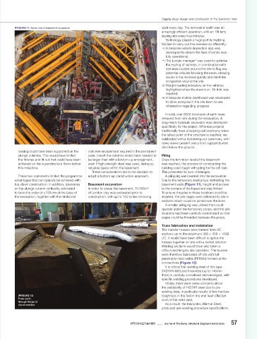
forces in them under vertical loads, even when load. The two cases are considered separately Six trusses were utilised in total, each FIGURE 11: Aerial view of basement excavation spoil every day. The removal of earth was an
considering a balanced arrangement such that as per the Building Regulations. The upward weighing over 60t. amazingly effi cient operation, with an 18t lorry
the support node was at the neutral axis. This vertical load case was demonstrated to not leaving site every four minutes.
issue was resolved by releasing the trusses exceed the vertical load from the building above Construction methodology Technology played a huge part in enabling
laterally at one end on directional bearings and therefore does not govern the design. Top-down versus bottom-up McGee to carry out this exercise so effi ciently:
(Figure 9), with propping provided by additional For the horizontal case, it was shown that the When constructing a deep basement, there are | A bespoke vehicle inspection app was
steels that can be seen adjacent to the truss in truss members had suffi cient capacity, but this two primary construction methods: top-down developed to ensure the eet of lorries was
Figure 10. scenario also applied a horizontal load into and bottom-up. The construction method and fully operational.
The building was classed as Consequence the truss support bearings, which had to be sequence are fundamental to the design of the | The Locatu manager was used to optimise
2
Class 2b as per Building Regulations Approved designed to resist this force. basement and must be considered upfront. the routing of vehicles, in combination with
Document A. However, the trusses are In addition to the horizontal forces from Top-down construction involves installing cameras located around the site to ag any
considered to be key elements and are capable a blast load case, the bearings had to be piles and plunge columns from ground level to potential vehicles blocking the route, allowing
of sustaining an accidental design loading designed to accommodate the maximum range basement-formation level, before casting the issues to be resolved quickly and minimise
of 34kN/m applied to the member and any of movement, along the axis of the trusses, that ground- oor slab. The ground- oor slab is then congestion around the site.
2
attached components. This design load is could be experienced in a re scenario due to undermined, excavating to the next basement | Weight loading indicators on the vehicles
assumed to act simultaneously with the other thermal expansion. This movement is on top slab level, and the rst basement level is cast. highlighted when the maximum 18t limit was
design loads on the building, but using an of the horizontal de ection experienced due to The process of excavation and construction of reached.
accidental design combination of actions. movement of the retaining wall. As such, the oors slabs is repeated until formation level is | A bespoke mobile dashboard was developed
In the case of a blast above the ballroom, this bearings allow for 280mm of positive movement reached. to allow everyone in the site team to see
applies a downward pressure in addition to the and up to 60mm of negative contraction. One of the major advantages of top-down information regarding progress.
vertical load of the building above the trusses. The bearings, weighing nearly 3t each, and construction is that work on the superstructure
This was shown to not exceed the ULS design the supporting capping beam and reinforced can occur simultaneously to construction of In total, over 8000 lorryloads of earth were
case for the trusses and did not govern the concrete corbels at either end were designed the basement, providing scope for programme removed from site during the excavation. A
design. to carry the loads of the trusses at the most savings. This method also negates the need for long-reach hydraulic excavator was developed
A blast within the ballroom could generate onerous position. The bearings were also a temporary propping system, as permanent speci cally for the project. Whereas projects
both a horizontal and vertical upward blast designed for maintenance and replacement. prop slabs are installed as the dig progresses, traditionally have a topping-out ceremony when
also helping to minimise ground movements. the tallest point of the structure is reached, we
However, these bene ts usually come at celebrated with a bottoming-out ceremony, with
FIGURE 9: Articulation of steel truss an increased cost of construction. Another news crews present and a time capsule buried
drawback of this method is that the vertical 35m below the ground.
tolerance of plunge columns can lead to loading could have been supported on the concrete encasement required in the permanent
large column areas on the lower oors of the plunge columns. This would have limited case, meant the columns would have needed to Piling
basement. the nishes and t-out that could have been be larger than with a bottom-up arrangement, Once the formation level of the basement
Bottom-up construction, on the other hand, achieved on the superstructure oors before even if high-strength steel was used, taking up was reached, the process of constructing the
involves a phased sequence of excavation this milestone. valuable space within the basement. building could begin with piling for the raft slab.
and installation of temporary props as the dig These considerations led to the decision to This presented its own challenges.
progresses to the full basement depth. This These two constraints limited the programme adopt a bottom-up construction approach. A piling rig was lowered into the excavation.
allows access to construct the foundations advantages that can typically be achieved with Due to the temporary steel props restraining the
before installing permanent prop slabs, working top-down construction. In addition, tolerances Basement excavation basement walls (Figure 11), height and access
from the bottom up. It also allows the dig to on the plunge column verticality, estimated In order to create the basement, 75 000m to the corners of the basement was limited.
3
progress faster than in the top-down method; to be in the order of ±100mm at the base of of London clay was excavated prior to To ensure the piles in these locations could be
however, work on the superstructure cannot the excavation, together with the reinforced construction, with up to 150 lorries removing installed, the pile cages were delivered to site in
start until after the basement dig is complete. sections which could be joined over the bore.
The positioning of the temporary props also A smaller piling rig was utilised that could
FIGURE 10: needs to be carefully coordinated to ensure the operate under the temporary props, and the pile
Installation of
steel truss basement can be constructed around them. locations had been carefully coordinated so that
The choice between bottom-up and cages could be threaded between the props.
top-down basement construction was not a
straightforward decision on this project. Initially, Truss fabrication and installation
the contractors, who the design team engaged The transfer trusses were formed from UC
with, preferred a top-down approach. However, sections up to the maximum 356 × 406 × 1299
later assessment found this option to be less UC. It would have been diffi cult to splice the
favourable for two main reasons: trusses together on site with a bolted solution.
1) Multiple transfer structures within the building Welding sections would have also been a
mean that load is concentrated in a handful diffi cult and lengthy site operation. The trusses
of the columns in the basement. For a top- were therefore fabricated off site with full-
down approach, the team explored using penetration butt welds (FPBWs) formed at the
2.4m diameter piles under these heavily connections (Figure 12).
loaded columns. However, these piles were It is critical that welding steel of this type
unable to support the large loads, meaning (HISTAR 460) and thickness (up to 140mm
additional temporary plunge columns would thick) is carefully considered and managed, with
have been needed to support the transfer speci c welding procedures developed.
structures at intermediate points before the Initially, there were some concerns about
raft slab was cast. Furthermore, the piles the weldability of HISTAR steel due to pre-
would have penetrated the Lambeth group existing data, in particular results of low fracture
and Thanet sands, requiring bentonite plant FIGURE 12: toughness in the fusion line and heat-aff ected
to stabilise them during construction. Truss weld – zone of the weld area.
2) Before the raft slab was cast and plunge through ange of As a result, the fabricator, Allerton Steel,
chord member
columns encased in concrete, only temporary produced pre-welding procedure speci cations
31 32
thestructuralengineer.org | July 2022 July 2022 | thestructuralengineer.org Journal of The Korea Structural Engineers Association 57
한국건축구조기술사회지
Londoner Hotel_TSE July 2022_The Structural Engineer.indd 31 22/06/2022 17:56 Londoner Hotel_TSE July 2022_The Structural Engineer.indd 32 22/06/2022 17:57