
Page 56 - 건축구조 Vol. 29 / No. 04
P. 56
The Londoner hotel Project focus Project focus The Londoner hotel
해외작품소개
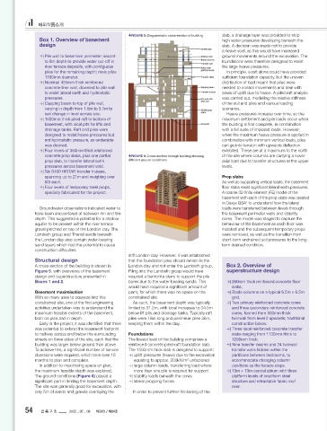
FIGURE 5: Diagrammatic cross-section of building slab, a drainage layer was provided to stop FIGURE 7: Prop slab load path river terrace deposits, with contiguous piles
Box 1. Overview of basement high water pressures developing beneath the for the remaining depth. The male piles were
design slab. A decision was made not to provide 1180mm diameter and spanned between the
a heave void, as this would have increased prop slabs resisting the earth pressures. In front
| Pile wall to basement perimeter: secant ground movements around the excavation. The of this sits a nominal 425mm thick reinforced
to 8m depth to provide water cut-off in foundations were therefore designed to resist concrete liner wall designed to resist hydrostatic
river terrace deposits, with contiguous the large heave pressures. pressures.
piles for the remaining depth; male piles In principle, a raft alone could have provided Tolerance on the piles was a key issue, as
1180mm diameter. suffi cient foundation capacity, but the uneven any lack of verticality had the potential to eat
| Nominal 425mm thick reinforced distribution of load meant that piles were into the 425mm liner wall and reduce the size
concrete liner wall, doweled to pile wall needed to control movements and deal with of the basement. For a basement of this depth,
to resist lateral earth and hydrostatic areas of uplift due to heave. A piled raft analysis this was fundamental, e.g. a 1:100 verticality
pressures. was carried out, modelling the relative stiff ness tolerance could result in an approx. 600mm
| Capping beam to top of pile wall, of the soil and piles and various loading reduction in basement size. To control tolerance,
varying in depth from 1.6m to 3.1m to scenarios. a guide wall was used and the piles were cased
suit change in level across site. Heave pressures increase over time, so the for the rst 15m. An allowable tolerance of
| 1500mm thick piled raft to bottom of maximum settlement and pile loads occur when 1:200 was speci ed for the cased section and
basement, with local pits for lifts and the building is rst complete, in combination 1:75 for the uncased. The speci ed tolerances
drainage tanks. Raft and piles were with a full suite of imposed loads. However, were generally met across the site.
designed to resist heave pressures but when the maximum heave pressure is applied in A reinforced concrete capping beam is
not hydrostatic pressure, as underside combination with minimum vertical loads, piles provided around the head of the piled wall
was drained. can go into tension with upwards de ection along the perimeter of the site. The capping
| Four levels of 350mm thick reinforced exhibited. These are at a maximum to the north beam is stepped in three locations to suit the
concrete prop slabs, plus one partial FIGURE 6: Cross-section through building showing of the site where columns are carrying a lower FIGURE 8: Non-prop slab connection details changing ground levels and the geometry of the
prop slab, to transfer lateral earth different ground conditions axial load due to transfer structures at the upper connection to ground- oor slabs and transfer
pressures across basement void. levels. trusses.
| Six S460 HISTAR transfer trusses,
spanning up to 21m and weighing over Prop slabs Transfer structures
60t each. As well as supporting vertical loads, the basement On the bedroom oors, columns were provided
| Four levels of temporary steel props, oor slabs resist signi cant lateral earth pressures. at regular centres hidden within partition walls,
specially fabricated for the project. A coarse 3D nite element (FE) model of the allowing shallow reinforced concrete oor slabs
basement with each of the prop slabs was created to be used. However, below the bedroom levels,
in Oasys GSA to understand how the lateral several column-free spaces were required to
1
Groundwater observations indicated water to loads were transferred between levels through allow for open-plan function and reception
have been encountered at between 4m and 6m the basement perimeter walls and stability spaces. The arrangement led to various transfer
depth. This suggested a potential for a shallow cores. The model was staged to capture the structures throughout the building, the majority
aquifer to be present within the river terrace behaviour of the basement as each oor was of which are located at ground and rst oor.
gravel perched on top of the London clay. The installed and the subsequent temporary props Incredibly, the building contains only two
Lambeth group and Thanet sands beneath were removed, as well as the transition from columns that extend continuously between the
the London clay also contain water-bearing short-term undrained soil pressures to the long- lowest basement level and roof.
sand layers which had the potential to cause term drained condition. The most noteworthy transfer structures are
construction diffi culties. located at ground level over the ballroom and
stiff London clay. However, it was established cinema, supporting the entire northern half
Structural design that the foundation piles should remain in the of the building superstructure. As the largest
A cross-section of the building is shown in London clay and not enter the Lambeth group. Box 2. Overview of column-free spaces in the hotel, these two
Figure 5, with overviews of the basement Piling into the Lambeth group would have superstructure design zones were stacked one above the other to
design and superstructure presented in required a bentonite slurry to support the pile minimise the need for further transfer structures
Boxes 1 and 2. bores due to the water-bearing sands. This | 260mm thick reinforced concrete oor within the basement.
would have required a signi cant amount of slabs. From this, more re ned individual FE models wall was required. The prop slabs are formed The ballroom oor, over the cinema, utilised
Basement maximisation plant, for which there was no space on the | Blade columns on a typical 6.5m × 6.5m of each prop slab were assessed. These models integral to the liner wall with reinforcement tying a series of concrete band beams to achieve
With so many uses to squeeze into this constrained site. grid. included both the vertical and lateral loads with them together and connecting back to the piled the spans required. Above the ballroom, large
constrained site, one of the rst engineering As such, the basement depth was typically | Two primary reinforced concrete cores envelope cases of the diff erent load combinations wall behind. This allows the safe transfer of the transfer structures were needed to support
activities undertaken was to understand the limited to 31.2m, with local increases to 34.5m and three secondary reinforced concrete considered to nd the most onerous design lateral earth pressures across the basement to the superstructure columns. A series of steel
maximum feasible extents of the basement, below lift pits and drainage tanks. Typically raft cores, formed from 300mm thick case. The RCSlab design layer in GSA was used the basement walls (Figure 7). trusses was chosen to provide this transfer,
both on plan and in depth. piles were 18m long and perimeter piles 36m, twinwall from level 2 upwards; traditional to generate the reinforcement required. For non-prop slabs, the edge detail was allowing for integration of the signi cant number
Early in the project, it was identi ed that there keeping them within the clay. construction below. Only four of the six basement slabs were used required to avoid attracting lateral forces while of ventilation ducts and services to the ballroom.
was potential to extend the basement footprint | Three local reinforced concrete transfer as full prop slabs. To the north of the building are maintaining a vertical support to the slab. This With spans of 21m and structural depth limited
to halfway across and below the surrounding Foundations slabs ranging from 1100mm thick to the ballroom and Odeon cinema, both double- was achieved by casting a corbel into the liner to 2.85m, the trusses were fabricated from large
streets on three sides of the site, such that the The lowest level of the building comprises a 1250mm thick. height spaces stacked on top of each either. This wall; the non-prop slab was then cast onto HISTAR 460 steel sections. This design allowed
building was larger below ground than above. reinforced concrete piled-raft foundation slab. | Nine transfer beams and 24 twinwall meant that the slabs at the rst (B1) and third (B3) the corbel with elastomeric strip bearings. A the headroom in the ballroom to be maximised,
To achieve this, a signi cant number of service The 1500mm thick slab is designed to support: transfer walls hidden within the basement levels only cover half the basement. movement joint between the slab edge and the which was a key requirement for the client.
diversions were required, which took over 18 | uplift pressures (heave) due to the excavation partitions between bedrooms, to For B1 it was decided that this slab would not liner wall was formed to allow the basement Due to the earth pressures, the head of
months to plan and complete. equating to approx. 200kN/m unfactored accommodate changing column be used as a prop slab. B3, on the other hand, wall to de ect under the earth pressures without the basement wall also needed propping at
2
In addition to maximising space on plan, | large column loads, transferring load where positions as the facade steps. is designed as a partial prop slab to the south, making contact and to avoid loading the non- this location. This couldn’t be achieved by the
the maximum feasible depth was explored. more than one pile is required for support | 13m × 13m central atrium with three with the remaining slab in the northeast corner prop slab (Figure 8). ground- oor slab due to a mismatch in levels
The ground conditions (Figure 6) played a | stability loads beneath the cores platform levels of cruciform steel designed not to prop the basement. caused by the sloping site. The initial proposal
signi cant part in limiting the basement depth. | lateral propping forces. structure and retractable fabric roof This variation in slabs that are propping and Basement walls was to use the trusses to prop the head of the
The site was generally good for excavation, with over. non-propping meant that careful consideration The basement walls consisted of secant piled wall. However, xing the ends of the trusses
only 5m of sands and gravels overlaying the In order to prevent further thickening of the of the connection details to the basement wall to 8m depth to provide water cut-off in the in position would have generated large axial
29 30
54 건 축 구 조 2022 _ 07 _ 08 제29권 / 제04호 thestructuralengineer.org | July 2022 July 2022 | thestructuralengineer.org
Londoner Hotel_TSE July 2022_The Structural Engineer.indd 29 22/06/2022 17:56 Londoner Hotel_TSE July 2022_The Structural Engineer.indd 30 22/06/2022 17:56