
Page 64 - 건축구조 Vol. 29 / No. 03
P. 64
Project focus Compton and Edrich stands, Lord’s Cricket Ground
해외작품소개
creating a common, clean aesthetic throughout
the stands.
An added benefit of the chosen solution
compared with others considered was the
minimum fabrication content, to the benefit of
the project overall.
The construction logistics of the site were
particularly challenging, with only a single
access point for vehicles that involved driving
through areas that were open to the public,
as the Indoor Cricket Centre needed to
remain in use throughout the majority of the
construction works. To complicate matters, the
single access point needed to feed four work
fronts for both steelwork and precast concrete
deliveries.
To construct the stands, Severfield primarily
– allowing both stands to be constructed at
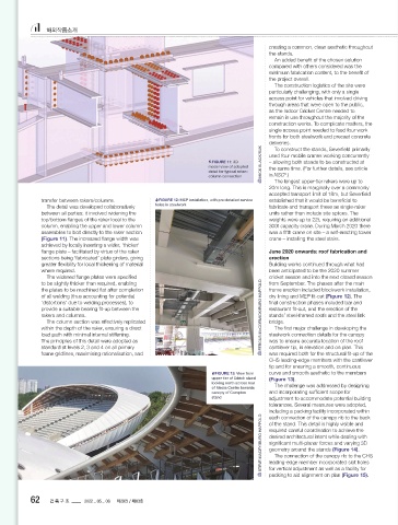
FIGURE 11: 3D MICK SLACK/SUK used four mobile cranes working concurrently
model view of adopted the same time. (For further details, see article
detail for typical raker– in NSC .)
5
column connection
The longest upper-tier rakers were up to
20m long. This is marginally over a commonly
accepted transport limit of 18m, but Severfield
transfer between rakers/columns. FIGURE 12: MEP installation, with pre-detailed service established that it would be beneficial to
The detail was developed collaboratively holes in steelwork fabricate and transport these as single-raker
between all parties; it involved widening the units rather than include site splices. The
top/bottom flanges of the raker local to the weights were up to 22t, requiring an additional
column, enabling the upper and lower column 300t capacity crane. During March 2020 there
assemblies to bolt directly to the raker section was a fifth crane on site – a self-erecting tower
(Figure 11). The increased flange width was crane – installing the steel stairs.
achieved by locally inserting a wider, ‘thicker’
flange plate – facilitated by virtue of the raker June 2020 onwards: roof fabrication and
sections being ‘fabricated’ plate girders, giving erection
greater flexibility for local thickening of material Building works continued through what had
where required. been anticipated to be the 2020 summer
The widened flange plates were specified cricket season and into the next closed season
to be slightly thicker than required, enabling from September. The phases after the main
the plates to be machined flat after completion frame erection included blockwork installation,
of all welding (thus accounting for potential dry lining and MEP fit-out (Figure 12). The
‘distortions’ due to welding processes), to final construction phases included bar and
provide a suitable bearing fit-up between the restaurant fit-out, and the erection of the
rakers and columns. FERGUS McCORMICK/BURO HAPPOLD stands’ steel-framed roofs and the steel link
The column section was effectively replicated bridge.
within the depth of the raker, ensuring a direct The first major challenge in developing the
load path with minimal internal stiffening. steelwork connection details for the canopy
The principles of this detail were adopted as was to ensure accurate location of the roof
standard at levels 2, 3 and 4 on all primary cantilever tip, in elevation and on plan. This
frame gridlines, maximising rationalisation, and was required both for the structural fit-up of the
CHS leading-edge members with the cantilever
tip and for ensuring a smooth, continuous
FIGURE 13: View from curve and smooth aesthetic to the members
upper tier of Edrich stand (Figure 13).
looking north across rear The challenge was addressed by designing
of Media Centre towards
canopy of Compton and incorporating sufficient scope for
stand adjustment to accommodate potential building
tolerances. Several measures were adopted,
including a packing facility incorporated within
each connection of the canopy rib to the back
STEVE MACEY/BURO HAPPOLD required careful coordination to achieve the
of the stand. This detail is highly visible and
desired architectural intent while dealing with
significant multi-planar forces and varying 3D
geometry around the stands (Figure 14).
The connection of the canopy rib to the CHS
leading-edge member incorporated slot holes
for vertical adjustment as well as a facility for
packing to aid alignment on plan (Figure 15).
32 33
32
62 건 축 구 조 2022 _ 05 _ 06 제29권 / 제03호 May 2022 | thestructuralengineer .org thestructuralengineer.org | May 2022
May 2022 | thestructuralengineer.org
Lords Cricket St_TSE May 2022_The Structural Engineer.indd 32 20/04/2022 09:50